Formation of outlines of rotary points |


|
|
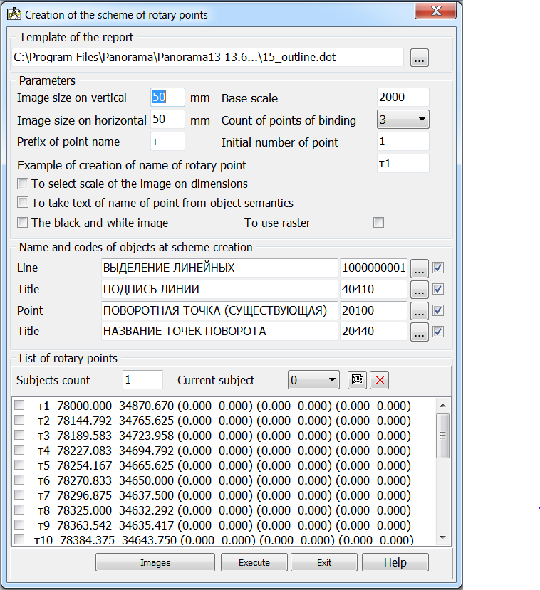
The size of the image of the outlines placed into the formed document is set by elements: Image size on vertical and Image size on horizontal . By default these sizes are equal 50mm. Base scale is requested from the main map of the document. It influences the image of an outline. If points of a binding have specified to a rotary point the scale of a picture is calculated by its dimensions in mm with that condition that the rotary point with points of a binding has been got onto a picture. From one up to three points of binding can be appointed to the rotary point. Number of points of a binding is set by means of the drop-DOWN list Count of points of binding . To each rotary point of object the name is appropriated. It is formed of a prefix and number of a point. The prefix is specified in an edited element: Prefix of point name . And in an edited element Initial number of a point the designation of the first point is necessary to specify. By default the first point has number 1, the second, accordingly, 2 and so on. The formed name of the first point can be seen in an element: Example of creation of name of rotary point . So that at formation of a name of a rotary point the text from 9-th semantics of object participated (the name own) include a tick: To take text of name of point from semantics . Black-and-white image tick influences an image of a formed picture. If tick is switched on the image is formed as black-and-white (printer-contour type), and at the switched off tick - the usual color image (contour type of a map). To use raster tick should be switched on for drawing a rotary point on a raster background. At creation of outlines can be applied: - Lines (the lines connecting a rotary point and points of a binding); - Titles of lines lengths; - Rotary point; - Title of a rotary point.
The choice of conventional symbols, management of structure of a picture is carried out in group: Name and codes of objects at scheme creation . List of rotary points is displayed in the group of the same name. At presence in object of subobjects (subjects) it is possible to use as rotary points of a point of subobjects. Switching between subobjects is carried out by means of the drop-down list: Current subject . The zero corresponds to a contour of object. At selection in the list of a line with a rotary point and its coordinates on a map the specified point is marked by blinking cross-hairs (cursor). If at a rotary point the points of binding have been specified they thus are marked on a map by labels: T1, T2, T3. Use the button For convenience of work with the list of rotary points on the list the contextual menu is organized. Way of start of a mode To print outline rotary points of object
|