Building of a profile in view of relative height of object |


|
|
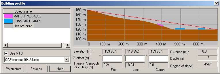
The result is displayed in a window as the diagram. Area objects without relative heights are designated on the diagram by ranges which color corresponds to the color of a map object. The height of range for the object having relative height is calculated in view of relative height of object. The list of objects displayed on the diagram is placed into the table. Building of a profile is made in view of curvature of the Earth if the corresponding option is set in parameters. The absolute height is calculated by a matrix with the least size of an element (more exact).
At the included option Use MTQ on the diagram the profile of a matrix of the qualities chosen from the list of matrixes is displayed. In the Depth window the value of a matrix of qualities is shown. At moving along a line with help of mouse in Elevation and Distance windows the values of heights at the first, last and current points of a line and also distance from the beginning of a line up to the current point in meters are displayed. In Profile height window the distance from the Earth surface in the current point of a profile up to a line connecting the first and the last points is displayed. In the table the object to which belongs a current point is highlighted. In the given mode there is an opportunity to rise / lower the initial, final, current points onto the certain height. For this purpose the necessary size must be entered into the appropriate field Z offset. In windows: There isn't enough for visibility the values are specified which need to be added to an initial, current or final point that direct visibility was provided. By pressing Parameters button it is possible to choose colors of the profile and of line of connection of the first - current - last points for displaying, to extinguish the image of auxiliary lines, to operate visibility of area objects. Building of a profile with new parameters is made by pressing Ok button. The mode carries out saving of the profile image in files of WMF, EMF format, that allows in further to print the image, to use it in WORD documents etc. For this purpose it is necessary to press Save as button, to choose a file name and the appropriate extension. For saving a profile into a text file the user should specify a discreteness of movement on object (a step of interpolation). At the included mode: Print length and number into a file the following data will be written down: number of a current point, coordinates X, Y, H and distance from the beginning of a profile up to a current point, at the switched off mode - only coordinates. If Use MTQ option is included into a text file the value of a matrix of qualities in a current point is written.
|