Checking of absolute elevations |


|
|
This task is intended for the checking of absolute elevations of objects and depths values of isobaths of a vector map's sheet.
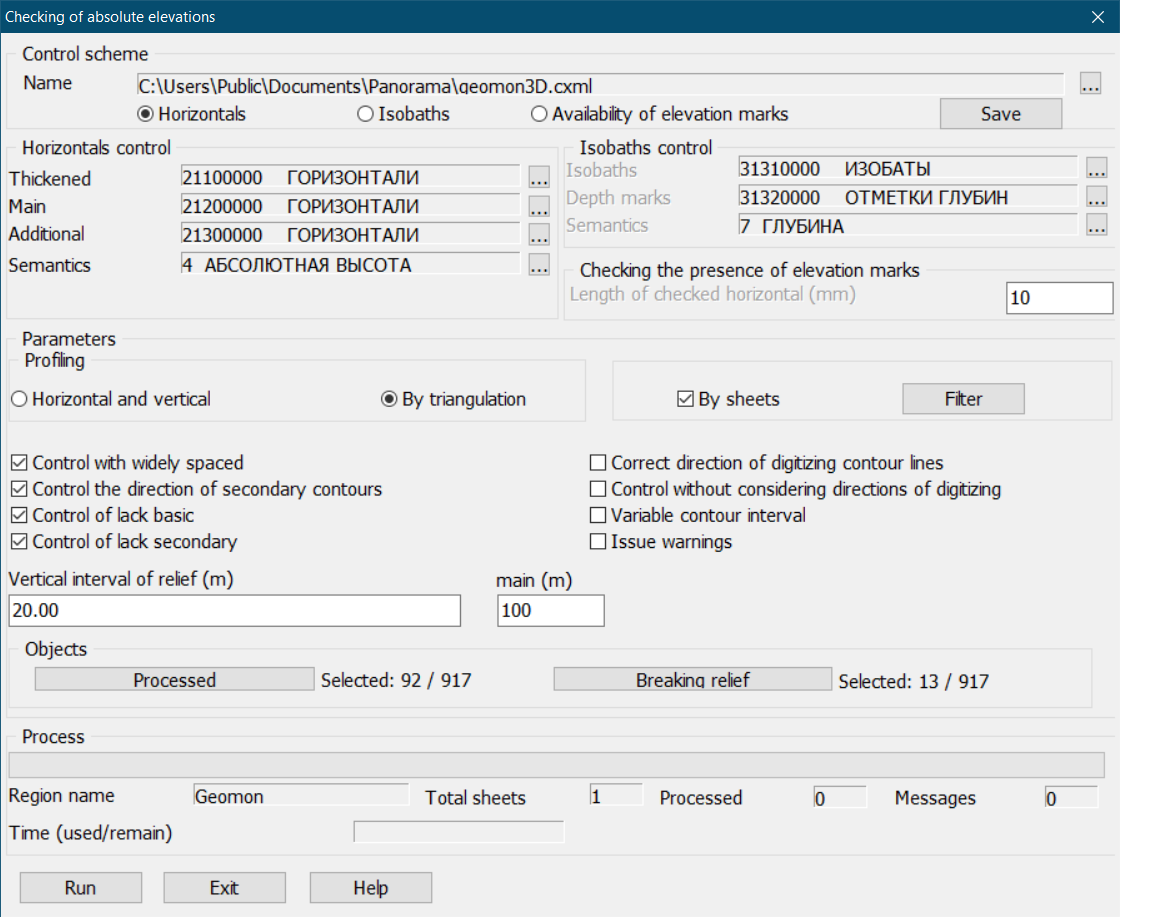
Dialog view:
Types of control: - control of horizontals; - control of isobaths; - control of elevation marks.
Contour lines control checks the elevations of thickened, main and additional contours, as well as other objects with the «absolute height» semantics. Control of isobaths checks the values of isobaths depths and marks of depths. Checking the elevation marks checks the presence of marks inside closed contour lines, as well as the planned position of the found marks relative to closed contour lines. To perform the task in different modes, it is possible to use control schemes. The types of control specified in the dialog, their parameters, as well as the composition of processed objects are saved in an XML file in the general folder of system tasks parameters «c:\Users\Public\Documents\Panorama\». The scheme file name has the «kwa» extension and is formed by the classifier name, for example - 50t05gm.kwa. The use of control schemes makes it possible to carry out a step-by-step check of relief objects in various modes. The control parameters specified in the dialog can be saved in the scheme file using the «Save» button in the «Control scheme» group. To select a previously customized scheme, use the «...» button in the «Control scheme» group. Buttons «...» in group «Horizontals control» allow to set codes of thickened, main and additional contours, and also semantics code «absolute height». Each of the given contour lines codes defines a group of classifier objects with the given code. For example, the code 21100000 defines objects of the classifier: CONTOURS THICKENED ON LAND, CONTOURS THICKENED ON ROCKS, CONTOURS THICKENED ON GLACIER. Buttons «...» in group «Isobaths control» allow to set codes of isobaths, depth marks, and also a code of semantics «depth». For the convenience of customizing control schemes, the buttons for selecting codes and semantics «...» in the groups «Horizontals control» and «Isobaths control» remain active regardless of the selected mode («Horizontals» «Isobaths») in the «Control scheme» group. In the field «Length of the checked horizontal (mm)» of the group «Checking the presence of elevation marks» is set the minimum length of the closed contour (Lmin) in millimeters of the map. This parameter is used when checking the planned position of the found mark of elevation relative to the closed contour enveloping it. If the length of the closed contour is less than Lmin, then the distance from the elevation found inside the contour to the contour itself is not checked. Otherwise (if the length of the closed contour is greater than Lmin), the distance from the mark to the closed contour enveloping it is checked. If the distance is less than 0.5 mm of the map (the mark «sticks» to the horizontal), then an error message is issued about the planned position of the elevation mark.
Modes of control of relief's objects are set in the «Parameters» group.
Control of absolute elevations is carried out by a method of profiling the objects of a relief. When constructing a profile, the elevations and other data of the objects are entered into the array. Next, the differences in the elevations of the adjacent points of the profile are checked. Profiling the objects of a relief can be carried out in two modes: - in horizontal and vertical directions; - by triangulation edges.
The mode of profiling is set in the «Profiling» group.
If the «Horizontal and vertical» profiling is set, then the control is performed by the map sheets. In this case, the test profiles pass through point objects and through three points of linear and areal objects. The first point - the center of the object dimension, the second and the third - top and bottom (for a horizontal direction) or left and right (for a vertical direction) dimension edge. The length of the test profile is equal to the length of the horizontal (vertical) sheet size.
If the profiling «By triangulation» is specified, then the triangulation is preliminarily built and then the test profiles pass by the edges of this triangulation. The control is carried out over the entire region, when constructing a profile, the elevations of objects of neighboring sheets are used. The vertices of triangulation are: a point object (elevation, GGS point, mark of water edge), a point of the metric of an areal object with an absolute height (lake, reservoir), a point of the contour line's metric.
For flat relief with a large number of elevation marks and a small number of isolines, the profiling «By triangulation» eliminates misses when searching for neighboring heights, which reduces the number of uninformative messages and facilitates the analysis of control results.
Profiling by triangulation is a more complex mode of control in comparison with horizontal and vertical profiling. In the case of region with a large number of sheets, the following messages can be issued to the operator:
- «Triangulation not buil»; - «Triangulation profiling will take a long time. Continue execution?».
These messages are issued in case of a large number of vertices obtained when processing objects with an absolute elevation of the entire region.
Operator actions on these messages: change the type of profiling (select «Horizontal and vertical») or divide the region into fragments (for example, process the region by sheets).
The "By sheets" mode allows you to select individual sheets of the region for processing by clicking the "Filter" button. If the "Horizontal and vertical" profiling type is set, then the "By sheets" mode is enabled and becomes unavailable for disabling. Map processing is performed for each sheet separately. If the profiling type "By triangulation" is set and the "By sheets" mode is disabled, then processing is performed in the region with the detection of erroneous elevation differences within the sheets, and also between objects of different sheets. If the profiling type "By triangulation" is set and the "By sheets" mode is enabled, processing is performed for each sheet separately. At the same time, the program does not detect erroneous height differences between objects of different sheets, but processing is performed 5-6 times faster than processing in the region, since triangulation is built for each sheet separately with a smaller number of edges (profiles).
«Control with widely spaced» - allows to take into account the presence of sparse contours on the map. The mode is used to reduce error messages in the presence of discharge of contours on the checked sheet. «Control the direction of secondary contours» - is used to check the direction of digitization of additional contours. If it is not specified, then additional contours are checked only in elevation. «Control without considering the directions of digitizing» - is used to reduce error messages at the non-observance of direction of digitizing contours. If the message «Mismatch directions of digitizing"»is issued into the control protocol, the following corrections of the map objects are possible: - change the direction of digitizing the contour; - change the value of erroneous elevation of one of the objects; - draw onto the map the missing contours, for example - around the point objects indicated in the message. «Variable contour interval» - for control of absolute elevations of a topographic map with variable contour interval. «Issue warnings» - disabled by default. Disabling this mode allows you to reduce the number of program messages, which makes it easier to analyze the control results. Warnings are «Discrepancy of elevations» messages that display the same elevation values for two objects. «Vertical interval of relief (m)» - for a topographic map with a constant contour interval, it is taken from the passport of the first sheet. If absent in the passport, it is taken from the control scheme. At control of absolute elevations of a topographic map with variable elevation of section, in the field «Vertical interval of relief (m)» When checking the absolute elevations of a topographic map with a variable contour interval, in the «Vertical interval of relief (m)» field should be, for example: -150 500 10 500 2000 20 2000 8000 50, where:-150 (min) 500 (max) 10 (section), 500 (min) 2000 (max) 20 (section) etc. When checking the absolute elevations of general geographical map according to the specified values of elevations, in the field «Vertical interval of relief (m)» should be, for example: 10 20 50 100 200 500 1000 1500 2000, where 10,20,50,… are the elevations of contour lines on this sheet. When checking the isobaths of topographical or general geographical map on preset values of depths, in the field «Vertical interval of relief (m)» should be, for example: 2 5 10 20 50 100 150 200, where 2,5,10, … - are the depths values of the isobaths. The «Processed» button in the «Objects» group - to set the composition of the checked map objects. By default, all linear, areal and point objects with the «absolute height» semantics are processed. The «Breaking relief» button in the «Objects» group is used to set the composition of linear and areal objects that break the sequence of elevations (for example, areal rivers, cliffs, quarries, ravines, and others). As a result of the task working, a protocol of control messages is created for the processed sheets of the region, which can be viewed in the «Map Editor» task - the «View error» mode. The protocol line contains information about the numbers and elevations of objects that are not coordinated by codes, elevation or direction of digitization. The sign «-» (minus) at the elevation value indicates the direction of digitization «from top to bottom», the sign «+» (plus) - to the direction of digitization «from bottom to top».
|