To build profile of a linear construction |


|
|
Building a profile is performed by the chosen object or a set of objects. As a result of an execution of the given mode the scheme of a linear construction is formed, on the basis of the coordinate description of an axis of a line. During formation the rectangular coordinates of a map are transformed to linear coordinates (X - distance along an axis of a line, Y - distance on a perpendicular from an axis of a line up to objects of a situation). Onto the formed scheme of a profile the all objects of the situation allocated (selected) to the moment of the beginning of operation are placed. In the metrics of linear object - the axis of a line should be present H coordinate. Just by coordinate of height the program counts a stationing along an axis of a line. Not closed three-dimensional objects are processed, at absence of Н coordinate in the metrics of object it is necessary to form it. For assignment of Н coordinateit is necessary preliminarily to form a matrix of heights of a relief. Then on a map to mark all linear objects at which it is necessary to form Н coordinate and to call the Convert to 3D mode from structure of Mark panel of the Map Editor. Results of construction are made in the form of the user map. The name of an output map and parameters of building a profile are specified by the user in dialogue of a mode. The user map is created with the classifier of the basic map of the document. For creation of the user map it is necessary to choose from the classifier the objects by means of which the lines will be drawn and titles are created. By Objects staff button the filter is set for formation of titles of objects which are transferred into an outline. The minimal absolute height displays value of the minimal height of the chosen object multiple to the vertical scale factor.
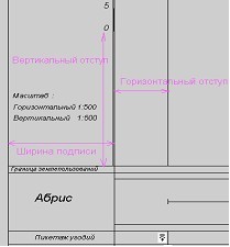
The horizontal scale is intended for record of objects into an outline. In outline line the objects marked on the main map and belonging to a zone around of chosen object are written down. The width of a zone around of the chosen object, i.e. amount and length of objects belonging to a zone, depends on height of a line of an outline and horizontal scale. The vertical scale is intended for formation of a profile. The scale-factor for display of heights is displayed according to vertical scale. Value of a step is shown in unedited window. The vertical scale begins or from value of the minimal absolute height or from zero. At the included option: Vertical scale with mark "0" the scale begins from zero, and into the column "Notes of axis» the difference between real height and value of the minimal absolute height is placed. Value of the minimal absolute height can be changed by the user. At presence of a matrix of heights it is possible to add points of extreme into the chosen object. For this purpose it is necessary to set height of extreme and a step of interpolation (promotion on object). In Precision of values dialogue windows the quantity of signs after a comma is specified for values of length, height. For the column «Precision of width in Angles,lines...» it is possible to choose a kind of record of corners in Format of angles window. It is necessary for User to set values of vertical and horizontal indentions, width of titles (see figure) and height of page. In dialogue the list of elements of appearance and edited windows for height of a line are set. Upon termination of process of building the values are placed into an INI-file of a map, if any line has been switched off then at the subsequent loading of the task the height is equal to zero. By pressing Default button the values of setting-up of elements of appearance and creations of the scheme of a linear construction will be set by the sizes specified in the program (as at initial loading). By pressing Cancel button thevalues which were on the screen before last editing are restored.
|